

Engineering case study
Custom wall-mounted kiosk: enclosure, USB controls and electronics integration
What began as a six-part enclosure print grew into a working hardware assembly: a redesigned body, eight illuminated controls, custom USB firmware, a metal keypad and a carefully routed wiring harness.
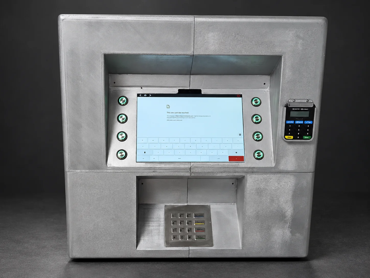
The assembled terminal with its tablet and controls fitted. AI-assisted cover treatment; original workshop photographs of the front and rear appear in the handover section below.
The project at a glance
Bondar Labs modified a customer-supplied enclosure design into a wall-mounted tablet kiosk, combining mechanical changes with physical controls and electronics. The intended application was access to online banking for people without a personal computer or smartphone. The client’s separate software developer handled the tablet application; our work covered the enclosure, button-controller firmware, wiring and hardware integration.
The project progressed through two main physical versions, with small fit-test parts between them. During the second phase we met the client in London, measured the supplied hardware, developed the assembly and tested it together at handover.
| Item | Project details |
|---|---|
| Starting point | Customer-supplied six-part enclosure model |
| Revised structure | Four main body sections, plus small mounts and retainers |
| Printing | Grey PLA; 0.4 mm nozzle; 0.2 mm layers; 100% infill for the final body |
| Assembly | M5 bolts, nuts and washers at revised fixing locations |
| Controls | Eight illuminated buttons, metal keypad and authentication-device holder |
| Controller | Arduino Pro Micro, ATmega32U4, 5 V / 16 MHz |
| Interface | USB keyboard events for the tablet application |
| Finish | Sanding, local automotive filler, primer and aerosol paint |
| Second-stage duration | Approximately two months of active collaboration |
| Second-stage labour | £1,000+, excluding components and the initial print stage |
| Handover | Tablet fitted and operation checked with the client |
From a print request to a complete hardware assembly
The first request was straightforward: print six supplied parts in grey PLA. At that stage, the customer already had a model and needed a physical enclosure to evaluate. That initial printing stage took approximately a week.
Around six months later, the client returned with a broader set of changes. An in-person meeting at their London office let us review the body alongside the equipment it needed to accommodate. The work expanded beyond reproducing the original files: component access, section joints, screen visibility, button operation and wiring all needed attention.
Some changes came directly from the client. Others were proposals from Bondar Labs, including a more secure mechanical pocket for the authentication device, revised fixings and real illuminated controls in place of imitation buttons and labels.
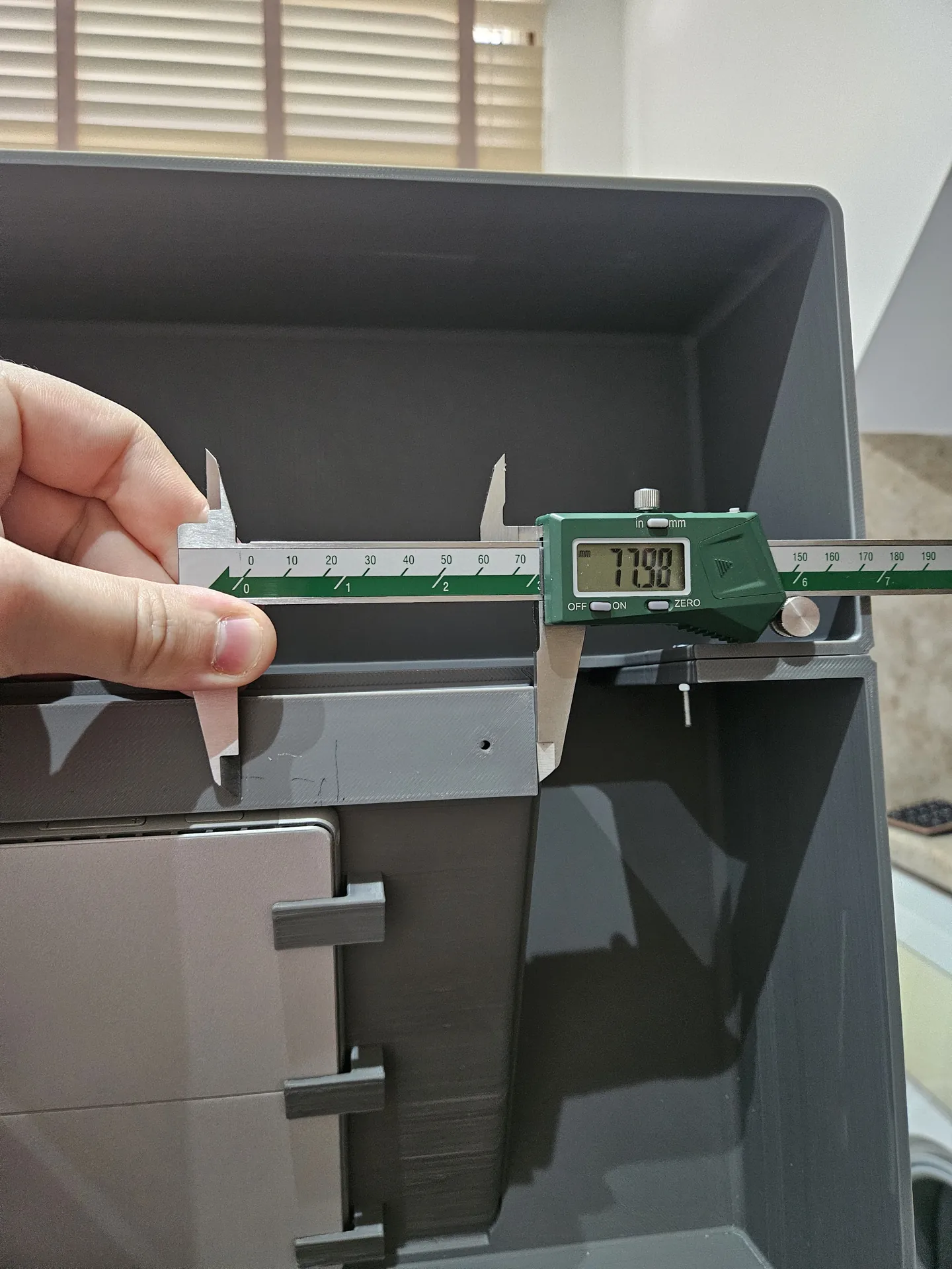
Measuring the hardware and testing the difficult fits
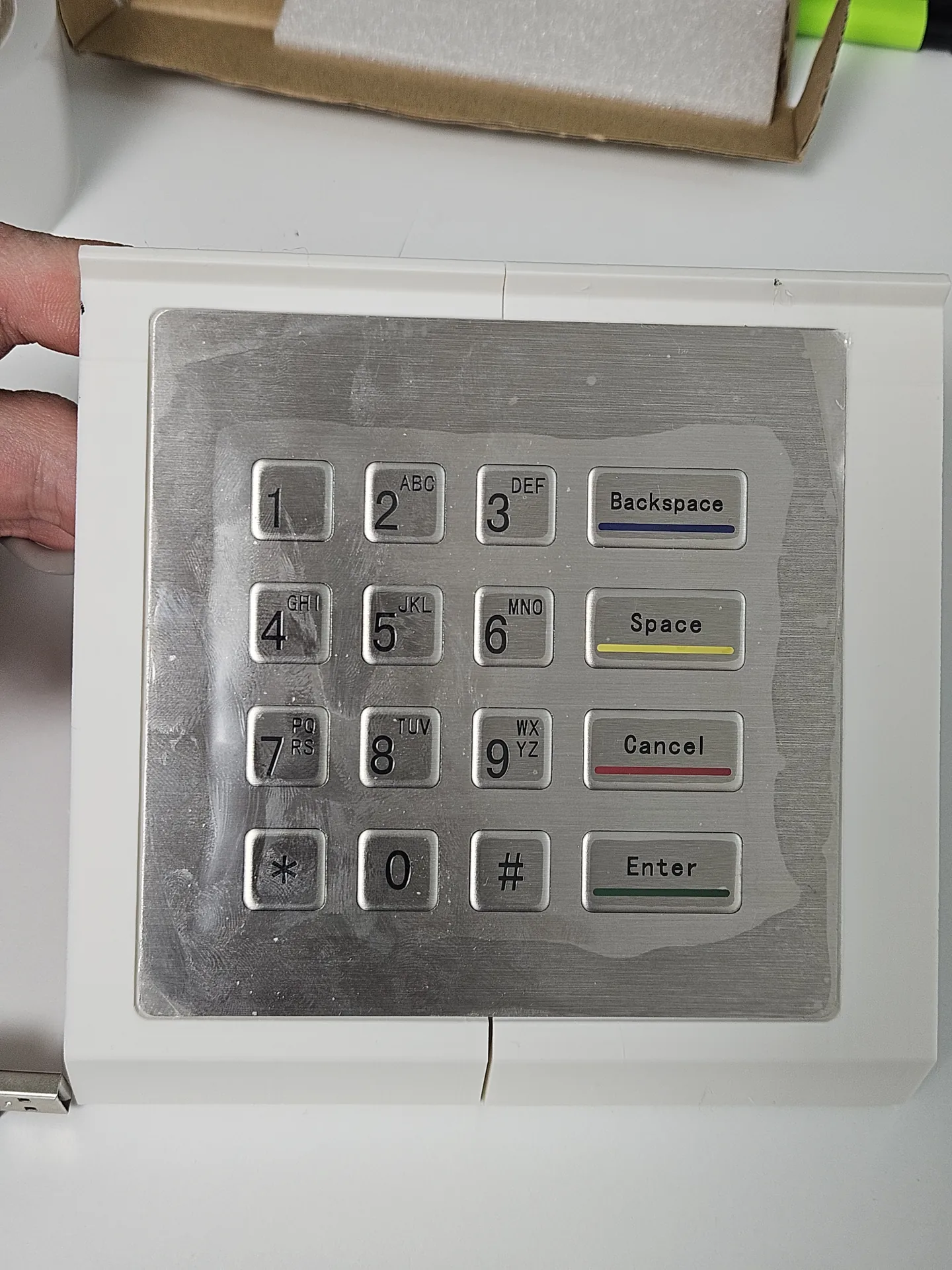
The enclosure had to accommodate a Microsoft Surface tablet, a metal keypad and a separate bank authentication device. The client supplied these principal devices; we sourced the buttons, controller, connectors, wiring and USB hub needed to integrate them.
Because the tablet remained with the client during development, measurements were recorded during the office visit and photographed for reference. These informed a small access opening for its power button and clearance around the camera and microphones. The screen recess was also opened out to improve the viewing angle from above.
A small keypad prototype before a large reprint
Rather than reprint the entire body to test the keypad, we isolated the relevant area of the model and made a small PLA test section. This gave access to both the visible opening and the underside of the keypad.
The trial exposed where mounting holes and clearances needed adjustment. Checking the cable route and fixing positions on a small part made those corrections much easier to evaluate before committing to the main enclosure sections.
A sliding pocket with a removable keeper
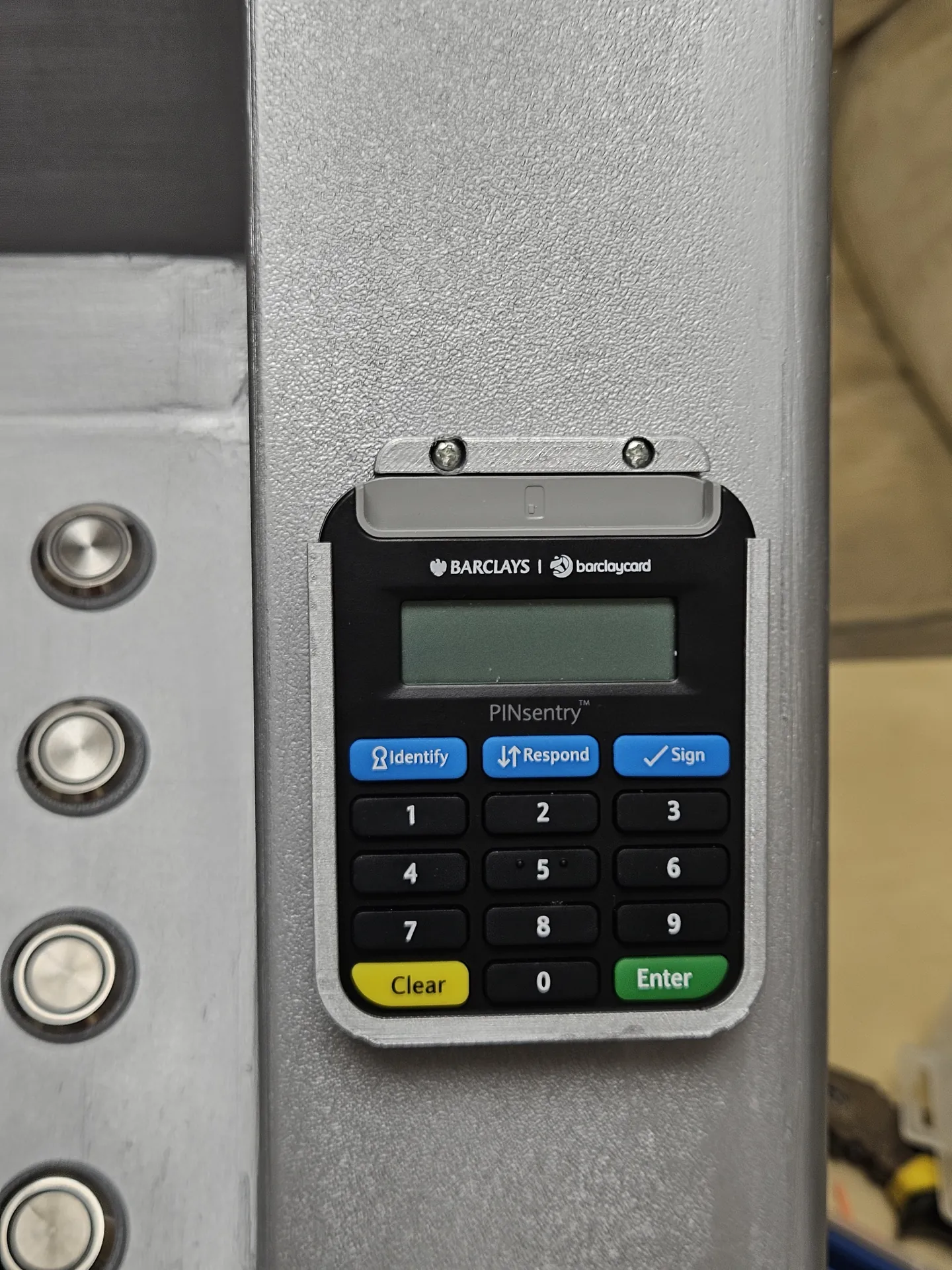
The client initially considered attaching the authentication device with double-sided tape. We instead designed a fitted pocket: the device slides down from the top, and a bolted retaining strip closes the exit above it.
That gives the device a defined position and a mechanical means of retention while leaving its display and buttons accessible. It also provides a deliberate way to remove the unit for replacement by undoing the retaining strip.
Reducing the main body from six sections to four
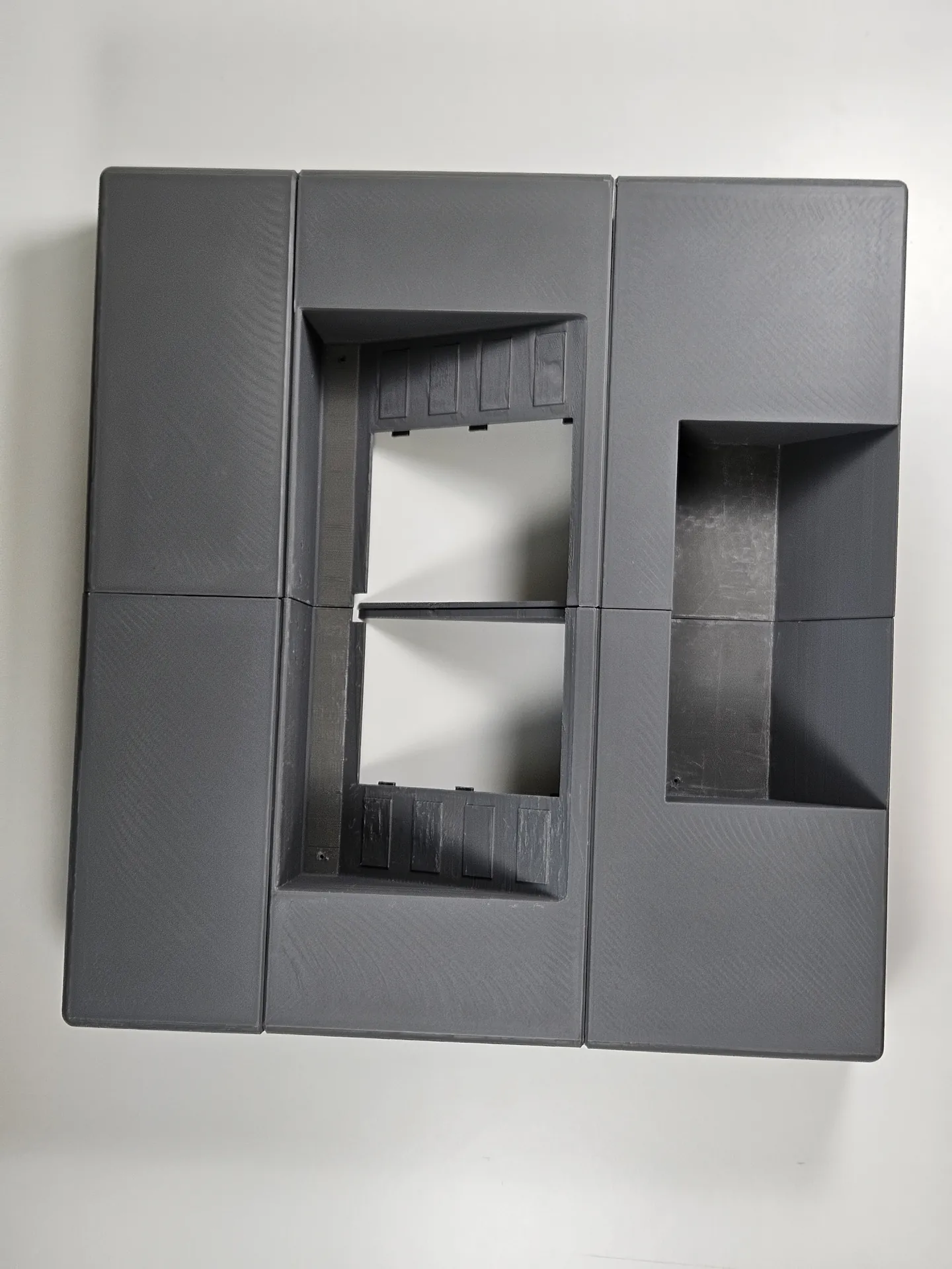
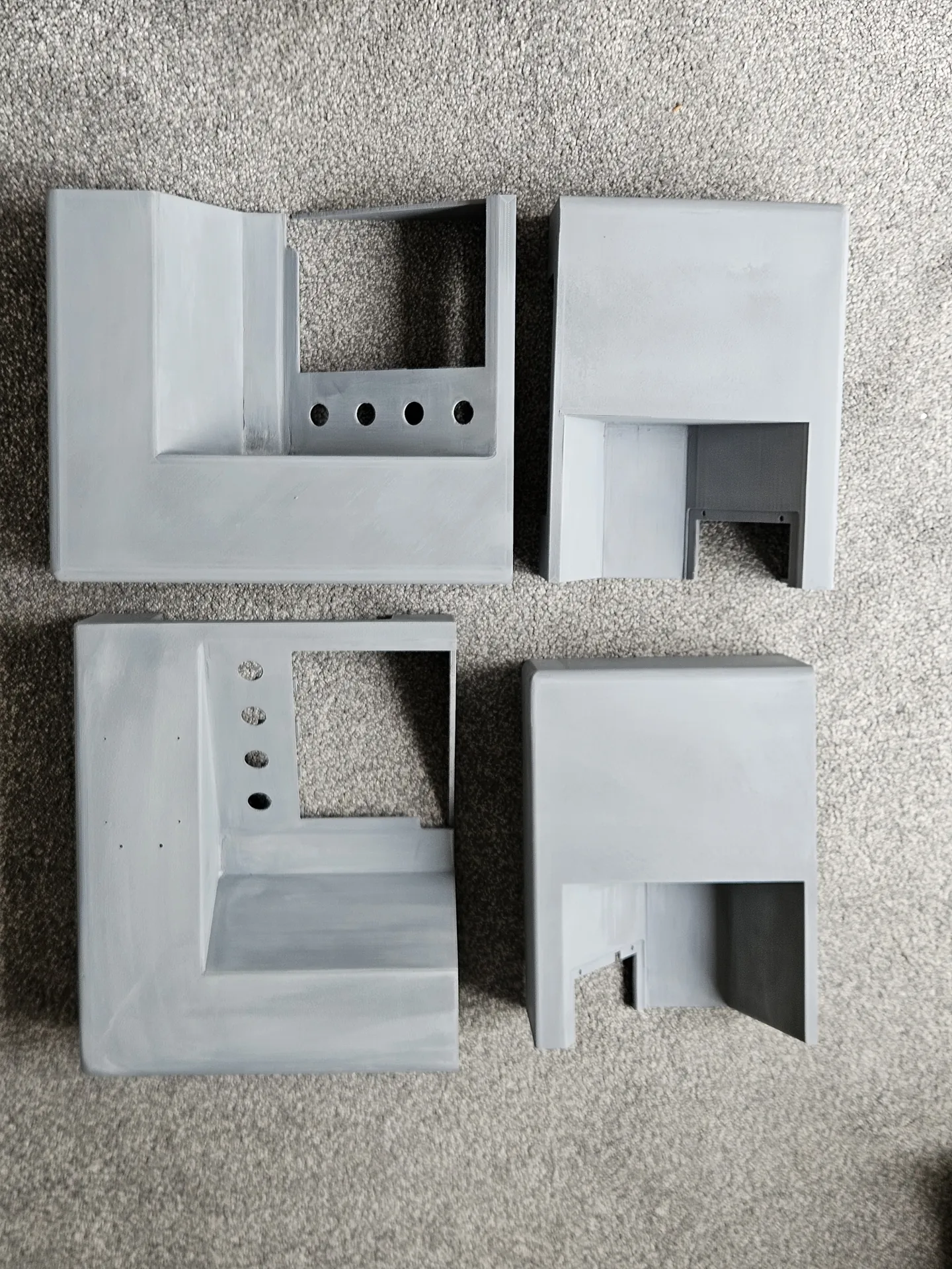
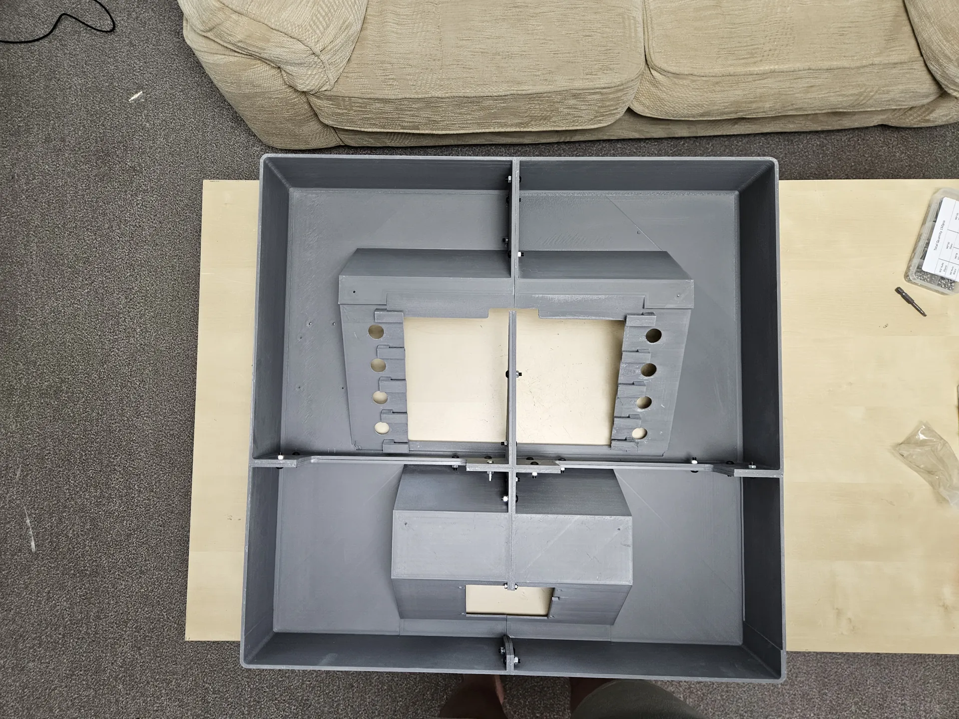
The next version merged adjacent geometry to reduce the body from six main printed sections to four. Fewer section boundaries meant fewer joints to align and finish, while the overall assembly remained practical to print and handle.
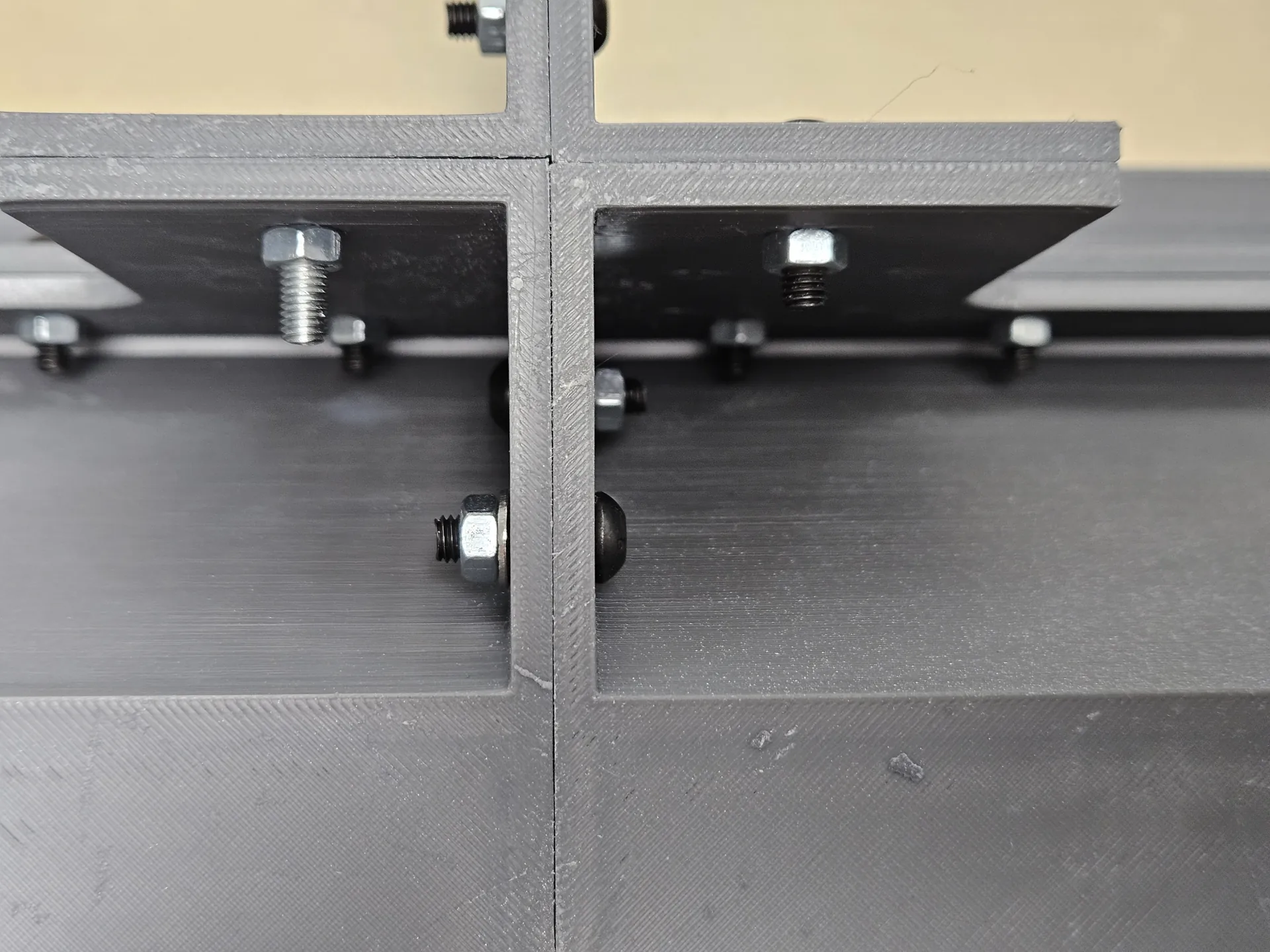
The original model used M3 fixing holes. We revised the connections for M5 bolts, washers and nuts, and moved fixing positions to support the important joints. This was a change to the joint layout as well as the bolt size: internal flanges and access for assembly had to work together.
The rear remained open. The intended mounting arrangement places it against a wall, with maintenance access obtained by taking the enclosure down. This also left the wiring and internal fixings accessible during construction.
Large-format 3D printing and a practical painted finish
Large-format printing allowed substantial enclosure sections to be made in one piece. The project used large Elegoo and Creality machines across its development; the final-body specification was grey PLA, a 0.4 mm nozzle, 0.2 mm layers and 100% infill.
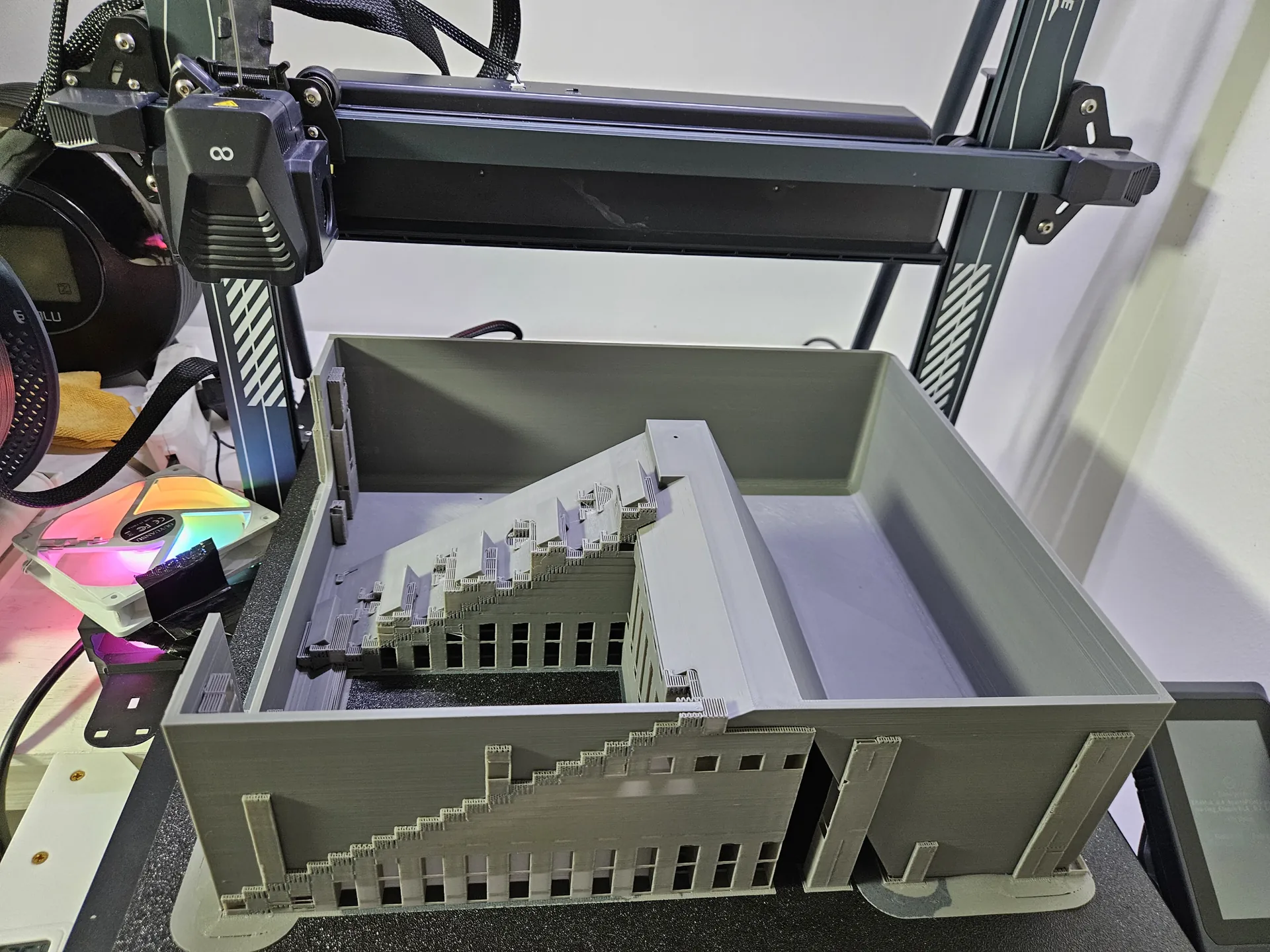
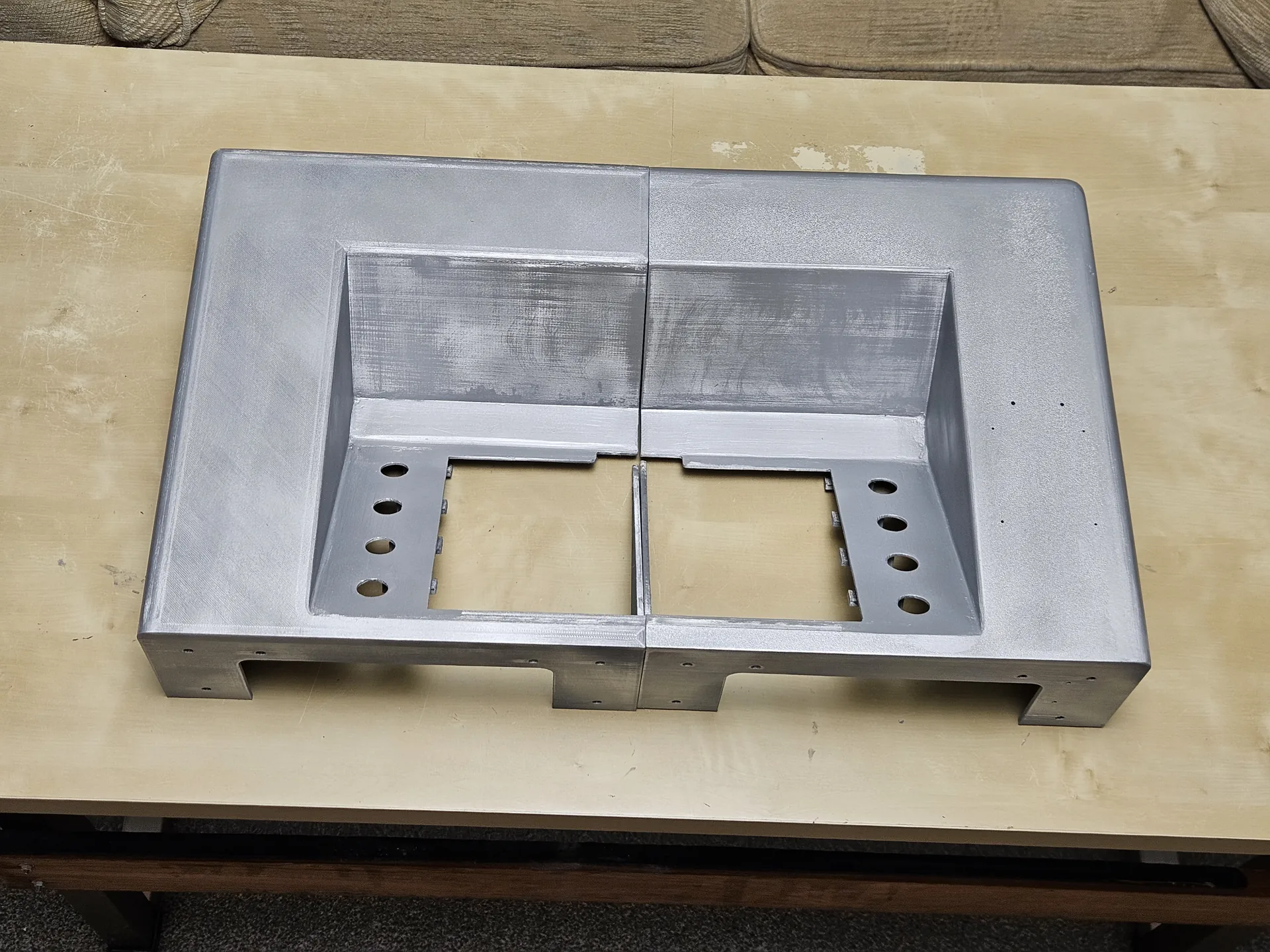
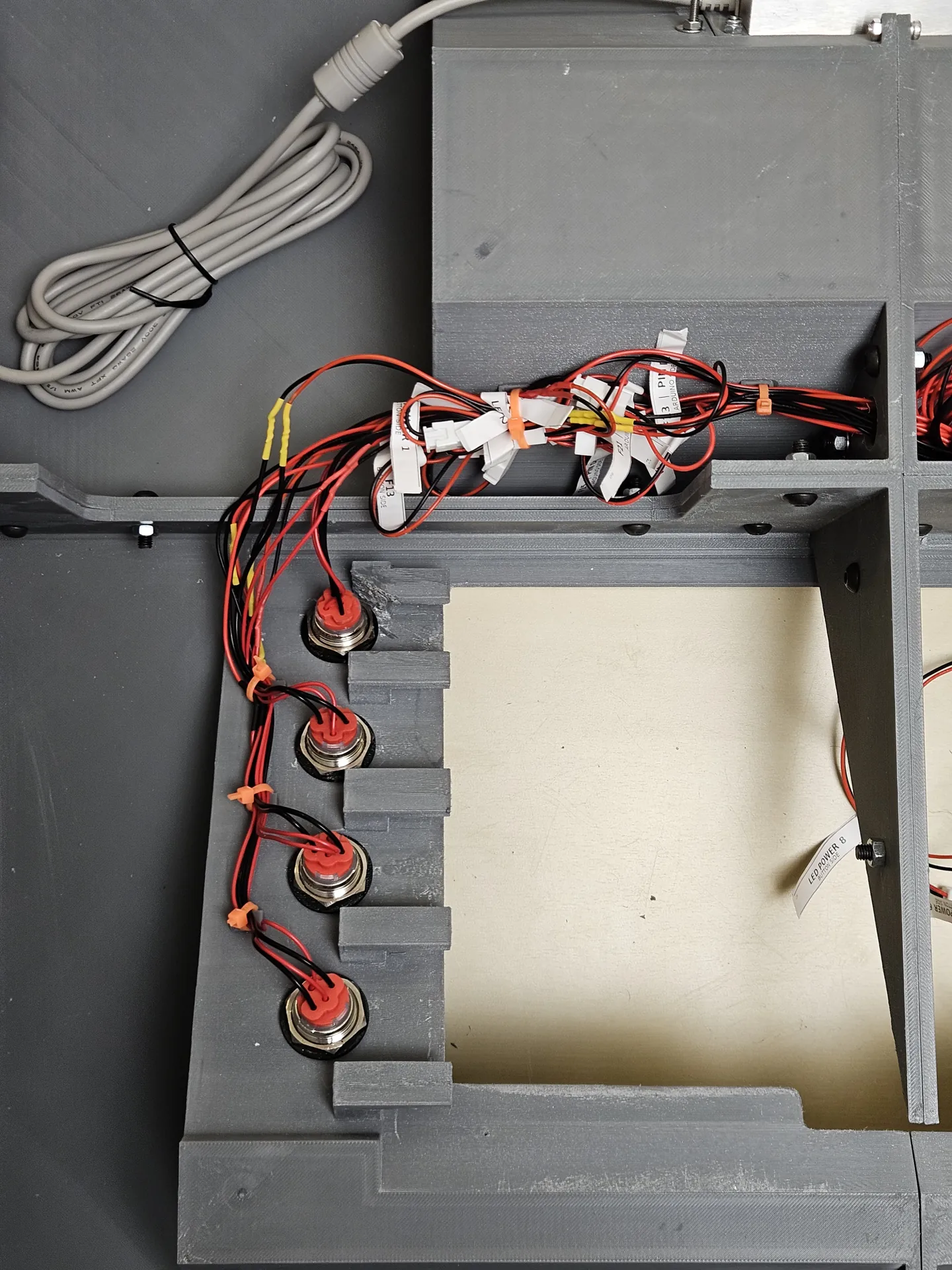
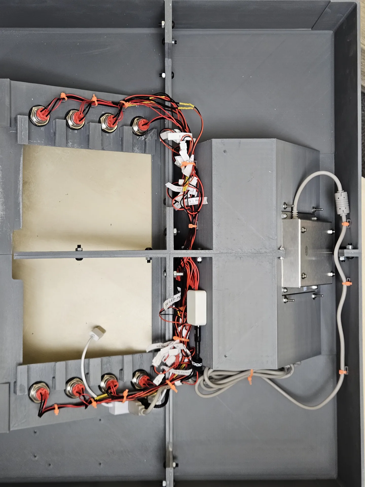
Recesses and overhanging details required support material, so printing was followed by removal and cleanup before the sections could be assembled. The production photographs show how much of the work sits behind the front surface: return walls, component recesses, support structures and internal joining features.
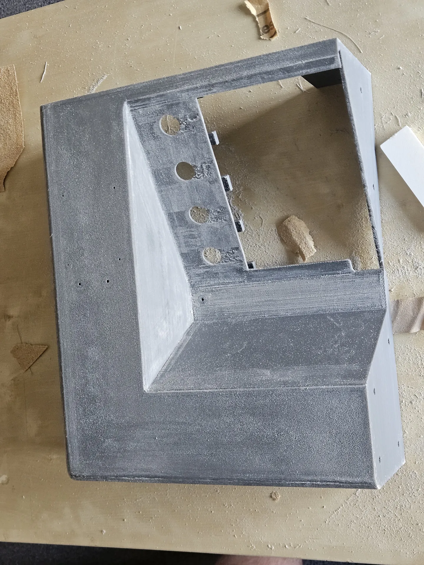
Once the parts were joined, we sanded the surfaces and used automotive filler locally around seams and difficult edges. Further sanding, primer and aerosol paint brought the body to the agreed finish.
The client’s priority was a usable, presentable assembly. We concentrated the finishing work where it mattered to the fit and visible edges, with some original print texture remaining on the broader surfaces. The photographs show the actual finish delivered.
Eight physical buttons with a standard USB interface
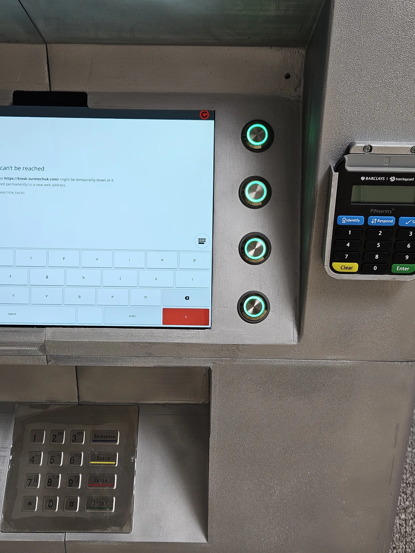
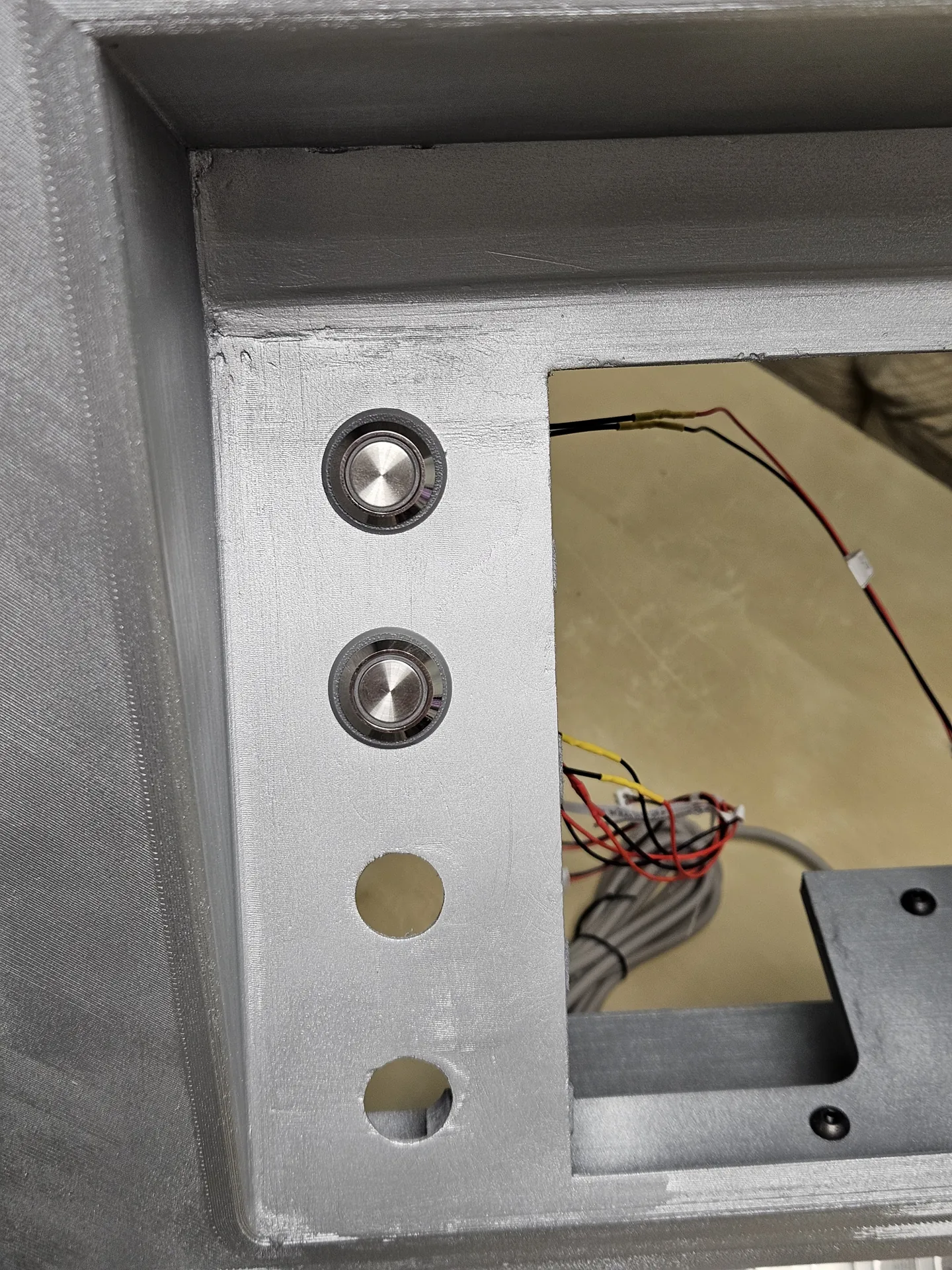
The original concept included imitation keys and labels. We proposed replacing these with eight illuminated physical buttons, arranged as four controls on each side of the screen. Button size and illumination were agreed with the client before the components were ordered.
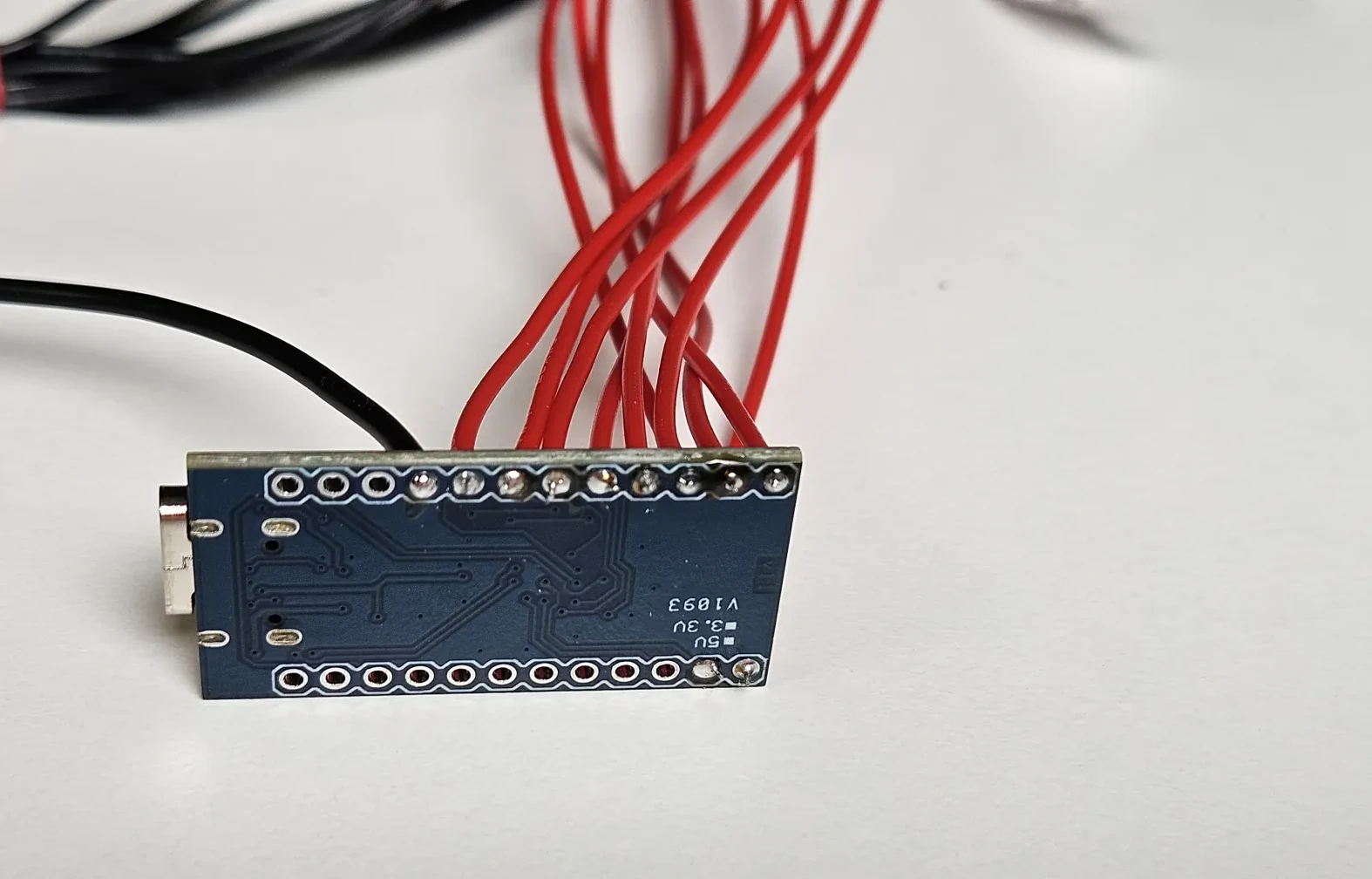
The controller is an Arduino Pro Micro based on the ATmega32U4, in the 5 V / 16 MHz configuration. We wrote its firmware so the tablet recognises it as a USB keyboard. Each button sends a distinct extended function-key event, allowing the application developer to associate that input with a software action.
For this project, the intended action was selecting the relevant banking web application. Our controller supplied the input events; the separate developer implemented the behaviour on the tablet.
Handling repeated presses and allowing for maintenance
The firmware included timing logic to limit unwanted repeated events from rapid presses or a held button. This helped define how the physical controls behaved when used by the application.
We also provided spare buttons and additional prewired controller connections. These made provision for replacement or later changes without requiring every connection to be soldered again inside the finished body.
Building and testing a labelled wiring harness
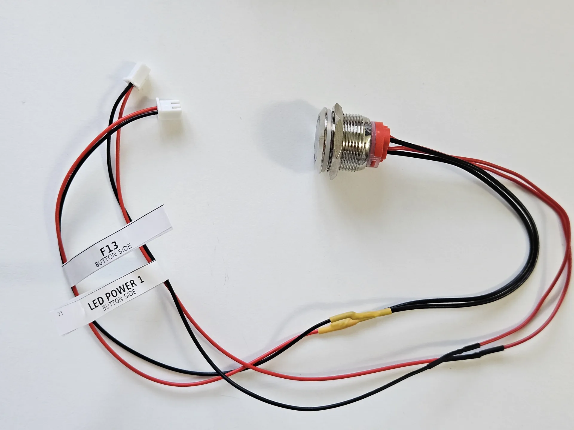
The button circuit and the button illumination use separate connections. Keeping those leads identifiable was important both during assembly and for future maintenance.
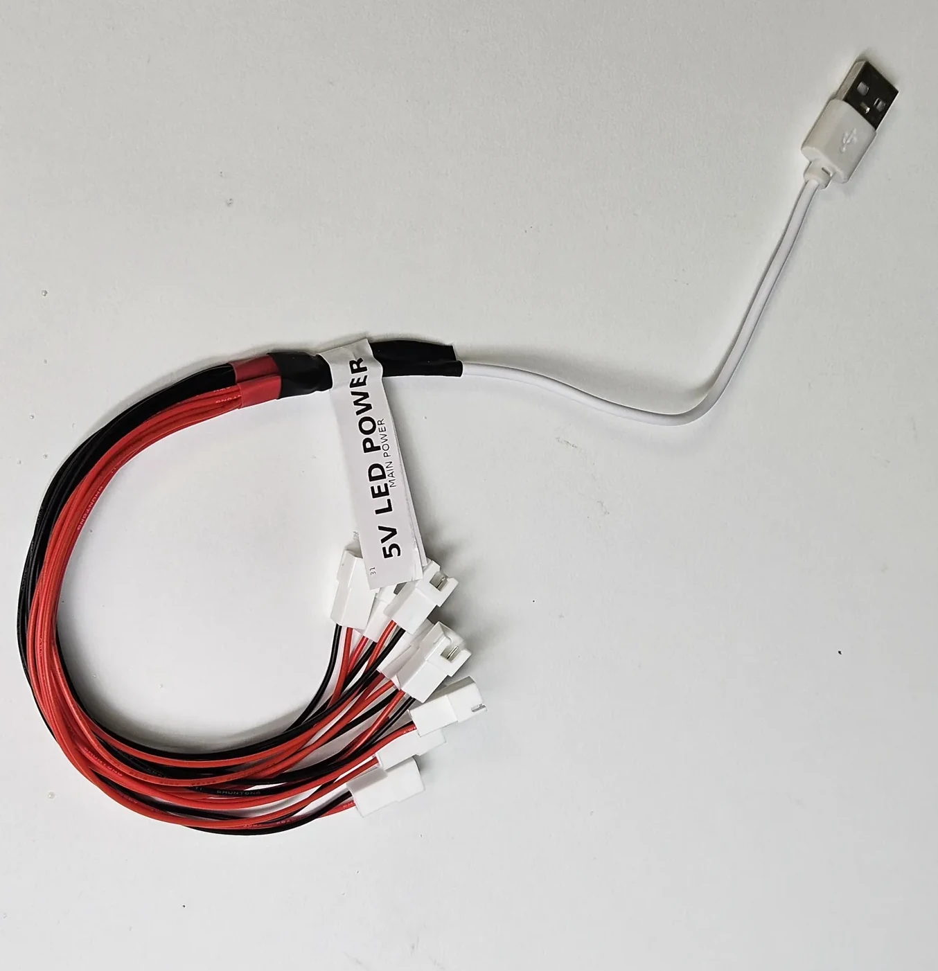
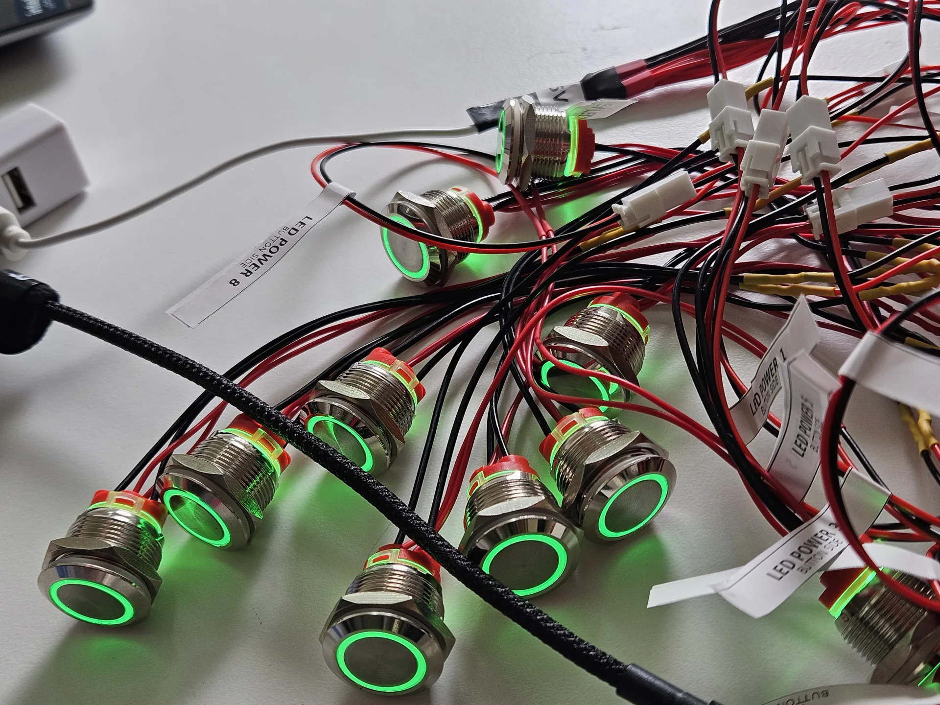
We cut and soldered the wiring, insulated connections with heat-shrink and added printed labels. The controller harness carries the button signals, while a separate USB power harness feeds the illuminated rings. The parts were prepared on the bench before being routed through the enclosure.
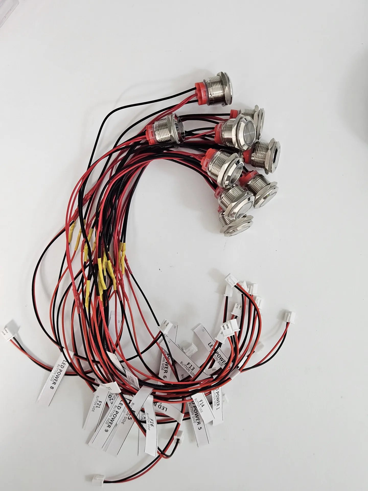
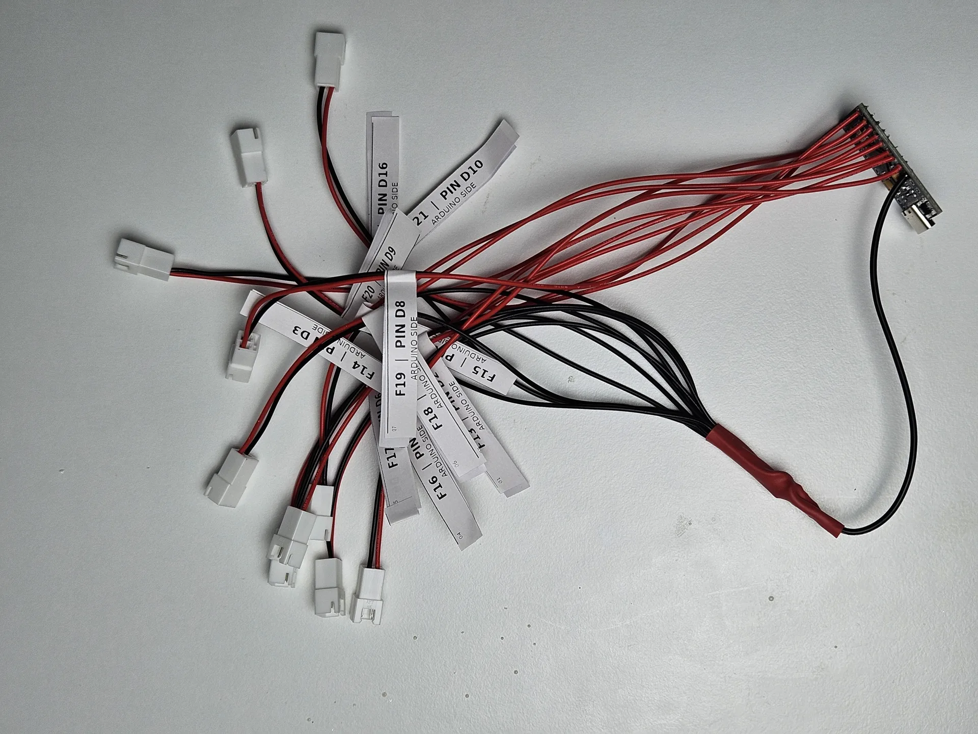
The complete set was connected and powered before installation. This allowed us to check the illumination, controller response and keypad operation while the connections were still accessible.
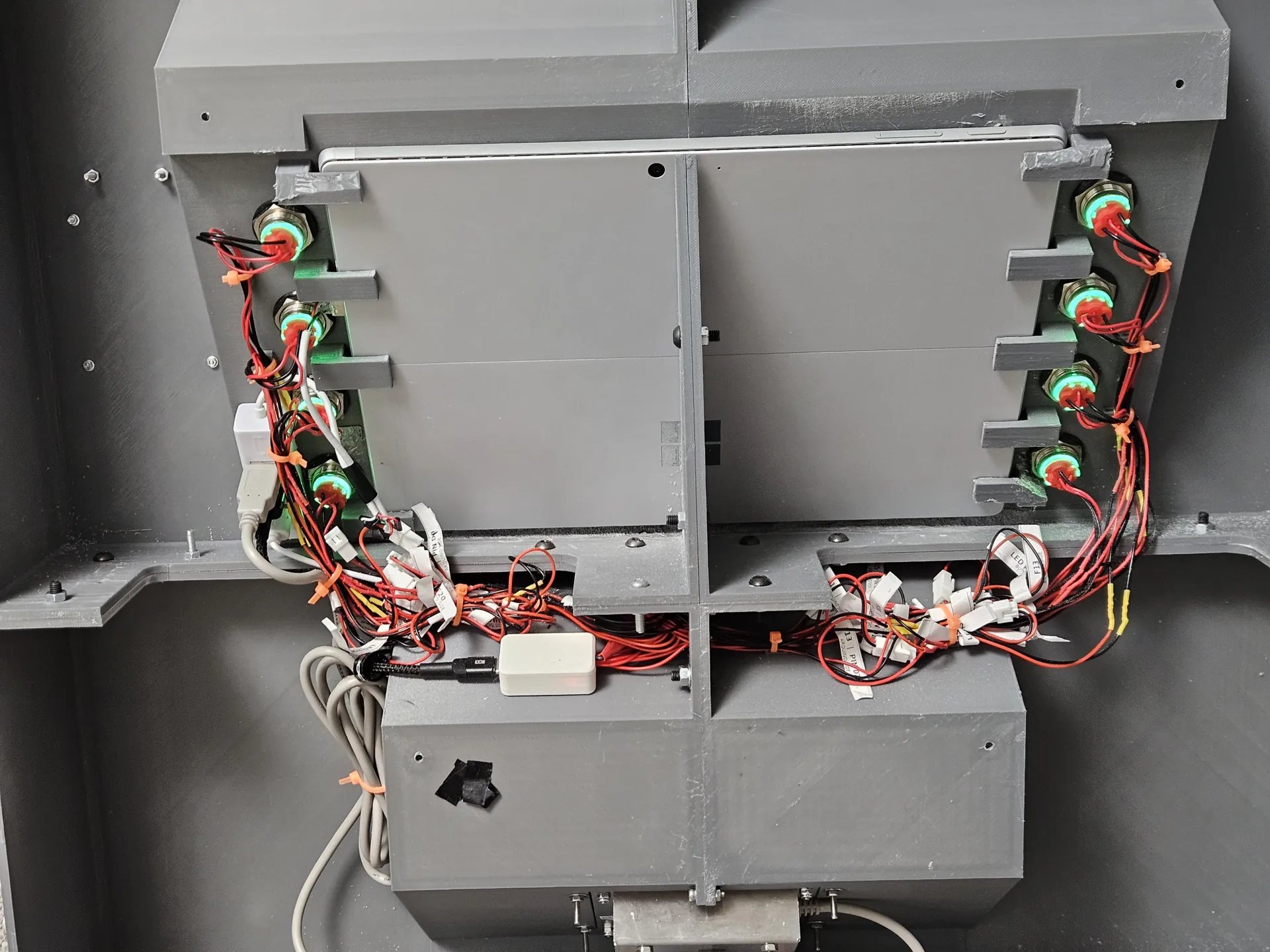
Only after these checks did the wiring move into the body. The controls were secured around the screen recess, with labelled connections arranged behind the front panel.
Retaining the tablet and sharing its USB connection
The tablet fits from the rear, sliding behind the front panel and into plastic retaining clips. These locate it in the screen opening. In the intended wall-mounted arrangement, the wall closes off access from behind; service work requires the enclosure to be removed.
The tablet had a single available USB Type-A port, while the assembly needed connections for the keypad, button controller and illumination. We therefore added a USB hub and positioned the connections within the enclosure.
The power arrangement has two paths: the tablet uses its own charger, and its USB connection powers the hub and attached accessories. There is no separate power supply for the button electronics or lighting. We checked the connected hardware using this arrangement during integration.
Documentation, final checks and client handover
Documentation supplied with the controller explained its input signals and operating logic so the application developer could use the buttons. The firmware source itself was not part of the handover.
At the final meeting, we fitted the tablet together with the client. They connected it to Wi-Fi and checked the operation of the assembly, confirming that they were happy with the result. This case study concludes at that handover; it does not document a subsequent shop installation.
The second stage involved approximately two months of active collaboration, including design changes, sourcing components, printing, finishing, firmware, wiring and assembly. The disclosed cost is £1,000+ for second-stage labour, excluding components and the earlier print-only stage.
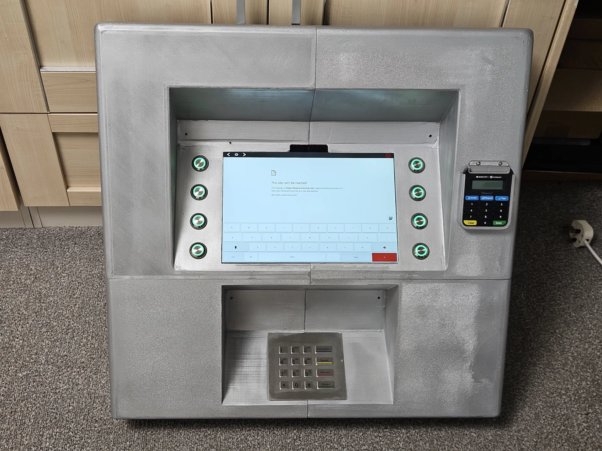
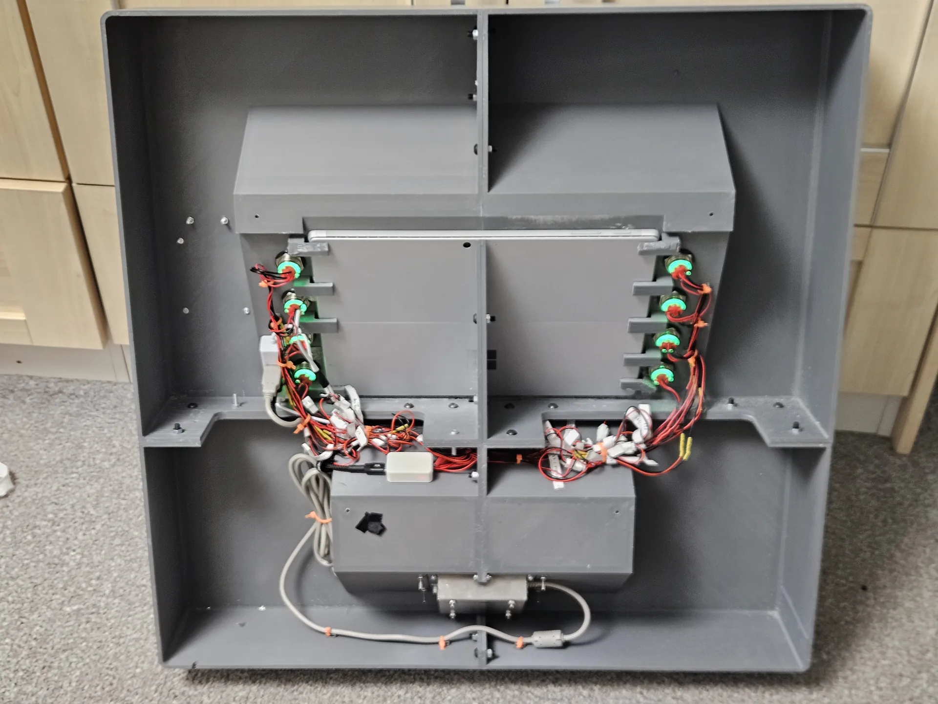
The main outcome was a complete hardware assembly developed around the client’s devices and requirements. Small fit prototypes, revised mechanical joints and bench-tested wiring helped bring the separate pieces together before the final tablet integration.
Planning a similar kiosk or electronics enclosure
This project shows the value of considering the enclosure and its contents together. A housing may need changes to its openings, mounting features, wiring routes and service access as the real components are fitted.
For a similar enquiry, useful starting information includes:
- The equipment models and the files or drawings already available.
- How the enclosure will mount, and how it should be opened for maintenance.
- The required buttons, connectors and viewing or access clearances.
- Which parts of the electronics and software are already covered by your team.
- The quantity, finish expectations, budget and delivery requirements.
Explore our 3D design and file support, FDM printing and work for business customers, or send a project brief to discuss the work needed for your assembly.
Related
FDM 3D Printing
See build size, material choices and common functional use cases.
PLA
A clear guide to one of the most common FDM materials.
Projects & examples
Browse more real-world projects across FDM, resin and batch production.
Get a Quote
Send your file or brief for an exact price and lead time.
Ready to print?
Send your file (or your idea) and we’ll reply fast with options and a clear quote.